Thursday, 20 April 2023

More details coming soon

 watch this space 

Ken

Tuesday, 8 December 2020

Peugeot Expert - Listing available PIDs

 Identifying PID groups

Data are logs created each time standard diagnostics are run in Diagbox.

So as a start, run a short diag for each of the main groups, Fuel circuit, Air intake, Electrical, Exhaust line, Cooling and Misc with the engine running if possible..

Running the Python script get parameter names.py, will create a text file with a list of the PIDs that were called in the TRC file, followed by a list of the parameters that were retrieved in the XML file.

Looking back through my old logs I found all sorts of stuff, like seatbelt info, button presses, key in starter position etc, It's possible that these were generated during actuator testing.

This is the list of my standard groups, which will give a starting point to find a specific PID 

Air Circuit

PID 21C98001

PID 21CA8001

PID 21CD8001

MP_REGIME_MOTEUR,Engine speed,*1 rpm@\*

MP_DEBIT_AIR_MESURE,measured air flow,*1 mg/impulse@\*

MP_CONSIGNE_DEBIT_AIR_a,air flow setting,*1 mg/impulse@\*

MP_PRESSION_ATMOSPHERIQUE,atmospheric pressure,*1 mbars@\*

MP_CONSIGNE_PRESSION_TURBO,turbo pressure reference value,*1 mbars@\*

MP_PRESSION_TURBO_MESUREE,turbo pressure measured,*1 mbars@\*

MP_CONSIGNE_POSITION_TURBO,turbo position reference value,%@\*

MP_RECOPIE_POSITION_TURBO,turbo position repeat,%

MP_RCOVANNETURBO,Turbo pressure electrovalve open cycle ratio,%

MP_CONSIGNE_POSITION_DOSEUR,Mixer position reference value,%

RECOPIE_POSITION_DOSEUR,Mixer position repeat,%

RCOCDEDOSEUR,Open Cycle Ratio for the air mixer electrovalve,%

MP_CONSIGNE_POS_VANNE_EGR,EGR valve position reference value,%

MP_RECOPIE_POSITION_VANNE_EGR,EGR valve position repeat,%

MP_COMMANDE_EGR,EGR valve control Opening Cyclic Ratio,%

MP_CONSIGNE_POSITION_BYPASS_REFROIDISSEUR_EGR,EGR exchanger Bypass position reference value,%

RECOPIE_POSITION_BY_PASS_REFROIDISSEUR_EGR,EGR exchanger Bypass position repeat,%

MP_TEMP_CARB_C9,fuel temperature *1@\*,°C

MP_TEMP_ADMI_DEBITMETRE,air flow sensor air temperature,°C

MP_TEMP_DEB,Air temperature in the inlet manifold,°C


Aircon

PID 21CD8001

MP_REGIME_MOTEUR,Engine speed,*1 rpm@\*

MP_TEMPERATURE_EAU_b,coolant temperature,°C

MP_PRESSION_CIRCUIT_CLIMATISATION_a,air conditioning circuit pressure@\*,bars

MP_CONSIGNE_VITESSE_GVM_01,Fan speed *1 setting@\*1,%

MP_MESURE_VITESSE_GMV,Measurement of the cooling fan speed,%

MP_CONSIGNE_VITESSE_GVM_02,Fan speed *1 setting@\*2,int

TENSION_CAPTEUR_NIVEAU_HUILE,Oil level sensor voltage,mV


Electrical

PID 0181

PID 21FE

PID 21C98001

PID 21CC8001

MP_REGIME_MOTEUR,Engine speed,*1 rpm@\*

MP_TENSION_BATTERIE1,battery voltage,V

MP_CONSIGNE_DE_CHARGE_PROGRESSIVE_ALTERNATEUR_a,alternator progressive charge reference value,%

TENSION_ALIMENTATION_5V_NUMERO_01,Supply voltage *1V n°*2@\*5@\*1,mV

MP_COMMANDE_RELAIS_PUISSANCE,power relay control,int

MP_ETATCDEDEM,Starter control status,int

MP_ETAT_DEMANDE_DEMARREUR,Status of the starting request,int

MP_COMMANDE_CHAUFFAGE_ADDITIONNEL_a,Status of the additional heating control,int


Exhaust line

PID 21C98001

PID 21CA8001

PID 21CB8001

MP_REGIME_MOTEUR,Engine speed,*1 rpm@\*

MP_ETAT_REGENERATION,Status of the regeneration,int

MP_MASSE_TOTALE_SUIE_DANS_FAP,total weight of soot in the PEF,g/l

MP_TEMPERATURE_FAP,Particle emission filter temperature,°C

MP_PRESSION_DIFFERENTIELLE_FILTRE_A_PARTICULES,difference in pressure between particulate emission filter input/output,*1 mbars@\*

MP_TEMP_ADMI_DEBITMETRE,air flow sensor air temperature,°C

MP_TEMP_DEB,Air temperature in the inlet manifold,°C

MP_DEMANDE_ACTIVATION_CONSOMMATEURS,Power consuming equipment activation request,int

VOLADDRESERVOIR,Amount of additive in the additive tank,ml

NIVEAU_MINIMUM_ADDITIF_ATTEINT,minimum level of additive reached,int

MP_VOLUME_TOTAL_ADDITIF_INJECTE,Cumulative total additive weight in the particulate filter,*1 g@\*

MP_VOLUME_RESERVOIR_ADDITIF,additive reservoir *1 volume@\*,ml

MP_DISTANCE_PARCOURUE_DEPUIS_ECHANGE_FAP,distance travelled since particulate filter replacement,Km

MP_DISTANCE_PARCOURUE_DEPUIS_DERNIERE_REGENERATION,distance travelled since the last regeneration,Km

DISTANCE_MOYENNE_ENTRE_LES_10_DERNIERES_REGENERATIONS,average distance between the last *1 regenerations@\*10,Km

MP_DEGRE_ENCRASSEMENT_FAP_EN_SUIES,degree of clogging of the PEF with soot,%

MP_DIST_AVANT_REMPL_FAP,Distance remaining before replacement of the FAP,Km

MP_AUTORISATION_REGENERATION,Authorisation of regeneration,int

MP_CAPC_EFFEC_COURT_TERME,Short term regeneration capacity,%

MP_CAPC_EFFEC_LONG_TERME,Long term regeneration capacity,%

CA_RICHESSE_CALCULEE_SONDE_A_OXYGENE,mixture calculated by the O2 sensor,int

CHAUFFSONDEO2,Activation of the heating of the oxygen sensor,%


Fuel circuit

PID 21C88001

PID 21C98001

PID 21CD8001

MP_REGIME_MOTEUR,Engine speed,*1 rpm@\*

MP_DEBIT_INJECTE_MESURE,measured injected flow,*1 mg/impulse@\*

MP_SYNCHRONISATION_AAC_VILEBREQUIN,camshaft/crankshaft synchronisation,int

MP_CONSIGNE_PRESSION_RAIL1,Setting for the fuel rail pressure,bar

MP_PRESSION_CARBURANT_MESURE,measured fuel pressure,bar

MP_COURANT_REGULATEUR_DE_DEBIT_IMV,Flow regulator current,mA

MP_ETAT_ACTIVATION_STRATEGIES_CORRECTION_OUVERTURE_INJECTEUR,injector opening correction strategies activation status,int

RCO_COMMANDE_REGULATION_DEBIT_CARBURANT,Open cycle ratio controlling the regulation of the fuel flow,%@\*

MP_TEMPS_INJECTION_CYLINDRE_01,cylinder *1 injection time@\* 1,ms

MP_TEMPS_INJECTION_CYLINDRE_03,cylinder *1 injection time@\* 3,ms

MP_TEMPS_INJECTION_CYLINDRE_04,cylinder *1 injection time@\* 4,ms

MP_TEMPS_INJECTION_CYLINDRE_02,cylinder *1 injection time@\* 2,ms

MP_TEMP_CARB_C9,fuel temperature *1@\*,°C

MP_KILOMETRAGE_FIN_DERNIERE_BOUCLE_RECALAGE_PICL,End mileage of the last PICL resetting loop,Km

MP_CORRECTION_ACYCLISME_INJECTEUR_1,Correction of acyclism on injector *1@\*1,µS

MP_CORRECTION_ACYCLISME_INJECTEUR_3,Correction of acyclism on injector *1@\*3,µS

MP_CORRECTION_ACYCLISME_INJECTEUR_4,Correction of acyclism on injector *1@\*4,µS

MP_CORRECTION_ACYCLISME_INJECTEUR_2,Correction of acyclism on injector *1@\*2,µS

MP_ECART_REGIME_MOTEUR_CYLINDRE_MOTEUR_1,Difference in engine speed on engine cylinder *1@\*1,rpm

MP_ECART_REGIME_MOTEUR_CYLINDRE_MOTEUR_3,Difference in engine speed on engine cylinder *1@\*3,rpm

MP_ECART_REGIME_MOTEUR_CYLINDRE_MOTEUR_4,Difference in engine speed on engine cylinder *1@\*4,rpm

MP_ECART_REGIME_MOTEUR_CYLINDRE_MOTEUR_2,Difference in engine speed on engine cylinder *1@\*2,rpm


Immobiliser

PID 21C88001

MP_ETAT_VERROUILLAGE_DEVERROUILLAGE_CALCULTATEUR,control unit condition,int

MP_ETAT_PROGRAMMATION_ANTI_DEMARRAGE,status of the coded engine immobiliser programming,int

MP_PB_TRANSMISSION_CODE_DEVERROUILLAGE,problems detected when transmitting the unlock code,int


Misc

PID 21C78001

PID 21C88001

PID 21C98001

PID 21CC8001

PID 21CD8001

MP_REGIME_MOTEUR,Engine speed,*1 rpm@\*

MP_SYNCHRONISATION_AAC_VILEBREQUIN,camshaft/crankshaft synchronisation,int

MP_VITESSE_VEHICULE_a,vehicle speed@\*,kph@\*

TENSION_SIGNAL_PEDALE_ACCELERATEUR_01,accelerator pedal signal voltage *1@\*1,mV

TENSION_SIGNAL_PEDALE_ACCELERATEUR_02,accelerator pedal signal voltage *1@\*2,mV

MP_POSITION_DE_PEDALE_ACCELERATEUR,accelerator pedal position,%

MP_INFO_POINT_DUR,Accelerator pedal point of resistance information,int

MP_TYPE_BOITE,Gearbox type,int

MP_RAPPORT_BOITE_DE_VITESSES,gear ratio *1@\*,int

MP_ETAT_CAPTEUR_POINT_MORT,Condition of the neutral sensor,int

MP_ETAT_CONTACTEUR_DE_FREIN_PRINCIPAL,principal brake pedal,int

PEDALE_FREIN_REDONDANT,redundant brake pedal,int

MP_VITESSE_CONSIGNE_REGULATION_DE_VITESSE,Cruise control speed setting,kph@\*

MP_ETAT_REGULATION_VITESSE,cruise control status,int

MP_VITESSE_CONSIGNE_LIMITATION_DE_VITESSE,Speed limiter speed setting,kph@\*

MP_ETATLV,speed limiter status,int

MP_ETAT_CONTACTEURS_FREIN_EMBRAYAGE,Status of the limiting of the vehicle speed,int

MP_PEDALE_EMBRAYAGE,clutch pedal,int

MP_VAL_POSITION_EMBRAYAGE,Value of the clutch pedal position,%

MP_ETAT_MOTEUR,*1 engine status@\*,int

MP_MESURE_MANOCONTACT_PRESSION_HUILE,oil pressure switch measurement,int


Sunday, 6 December 2020

Finding Peugeot Expert extended PIDs for display in the Torque App

Overview

My current van is a 2015 Peugeot Expert 2.0. The engine is and AHZ DW10CD 129bhp with a Delphi DCM3.5BR2 (branch 2). Usually I would use the FAP app to view live DPF regeneration parameters, however the ECU was updated a year ago, and it stopped working. Numerous requests to the developer have been ignored, so I decided I needed anther approach.

After initially using a OBD2 splitter cable with a Bluetooth adapter monitoring OBD2 requests and responses from Diagbox, I realised that Diagbox already logs the data, and that it is possible to figure out the proprietary PIDs.

The two key file types, *.trc and *.xml, are stored at c:\AWroot\dwtr\SpareTrace

The trc files log the raw ODB2 request and response sent to the ECU when you run a paramter test is diagbox.

This is the typical output

<ECUFrames Timestamp="1682">

<ECUFrame Dir="Sent">QFF0621C98001</ECUFrame>

<ECUFrame Dir="Received">R61FF03290000FF01FFFFFF28013301340038FFFFFFFFFFFFFFFFFFFFFFFF43FFFF000089008B008A0086FFFFFFFF551F4C1F5B1F171F3B3D103D103F9040003E803E803E403E403E503E003CC03CC040F040F040F03FF03EC03EC03E403E403FD03F703EF03EF000013AA001F4020801DB01F8</ECUFrame>

<ECUFrames Timestamp="2413">

<ECUFrame Dir="Sent">QFF0621C98001</ECUFrame>

<ECUFrame Dir="Received">R61FF032A0000FF01FFFFFF270133012F0037FFFFFFFFFFFFFFFFFFFFFFFF43FFFF000089008A00890088FFFFFFFF551F5C1F221F4C1F483D103D103F9040003E803E803E403E403E503E003CC03CC040F040F040F03FF03EC03EC03E403E403FD03F703EF03EF000013AA001F6020801DA01F7</ECUFrame>


The timestamp is in ms since the logging started, the request sent "QFF0621C98001" consists a header and the actual PID 21C98001.

The response is a header 61FF and a long string of hex results. In this case 21C98001 is used to retreive fuel system parameters eg fuel pressure & injection timings. So even if only one paramater is required, the whole lot are retrieved. There can be multiple request/response frames per timestamp.


Diagbox will produce an eqivalent XML file from this trc file, as an intermediate step to produce graphs of the data.

This is the typical output

<ChannelHeader Id="0" Mnemo="MP_REGIME_MOTEUR" Label="@P7917-POLUXDATA" _Type="FLOAT" Unit="@P8673-POLUXDATA@\*" MinVal="-340282346638528860000000000000000000000.000000" MaxVal="340282346638528860000000000000000000000.000000">
<DiscreteLegend>
<DiscreteValue Label="@V" MinVal="0.000000"   
MaxVal="8001.000000"/> <DiscreteValue Label="@P8038-POLUXDATA" MinVal="-340282346638528860000000000000000000000.000000" MaxVal="340282346638528860000000000000000000000.000000"/> </DiscreteLegend>
</ChannelHeader>

<Points>  

<Point Value="809.000000" Timestamp="0"/>

<Point Value="810.000000" Timestamp="1682"/>

<Point Value="806.000000" Timestamp="2413"/>

<Point Value="805.000000" Timestamp="3204"/>

In this case the PID has been identified as MP_REGIME_MOTEUR, which is actually revs. Note that the time stamp starts at zero, whereas the actual timestamp should start at 1682, as per the trc file. So we can see that the revs changed from 809 to 810 between the 1st and 2nd timestamp. We can assume that the revs are stored in 2 bytes, so that would equate 0329 and 032A in hex. As it happens start of the 1st response above is R61FF0329... and the 2nd is R61FF032A.. So we can see that ignoring the header, bytes 0 and 1 contain the data for revs. 

In Torque extendedPIDs this response location can be referenced as A,B or raw R0,R1. So the basic config would be PID 21C98001 with formula INT16(A:B)

Obviously this was an easy PID to find, and not really that useful because it's part of the standard PID anyway, but it demonstrates that this data can be easily mined.

Identifying parameter names

As can be seen in the xml files, the names of the parameters are in French e.g.

<ChannelHeader Id="0" Mnemo="MP_REGIME_MOTEUR" Label="@P7917-POLUXDATA" _Type="FLOAT" Unit="@P8673-POLUXDATA@\*" 

However the text label referred as @P7917-POLUXDATA is a reference to a translation file located at c:\AWRoot\dtrd\trans

In this case the english file is POLUXDATAen_GB.DU8. This is a proprietary format as follows.

4 byte Header ox14231423, 4 byte integer of the total number of records. Then at position 0x64 a series of 4 byte integers pointing to the start location of each string record. I wrote a rough python script decode_du8.py to extract this to a csv file and then imported into a Sqlite database polluxdata.db

To help reading the xml file the Python script update pollux.py cycles through the xml files, replacing the @nnnn-POLUXDATA references with the english labels (remember to back the files up first)

After processing you should now see more user friendly labels e.g.

<ChannelHeader Id="0" Mnemo="MP_REGIME_MOTEUR" Label="Engine speed" _Type="FLOAT" Unit="*1 rpm@\*" 


Monday, 28 August 2017

Pebble Steel improvised charging cable.

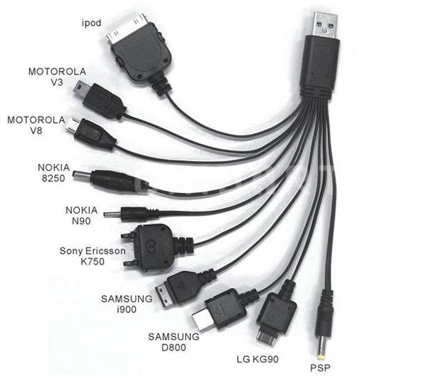
Every trip stuff breaks or gets lost or gets left at home.  The first thing on this trip was the realisation that I'd brought the wrong cable for my Pebble steel.  Getting a replacement on the road will be pretty much impossible so I needed to get an interim fix.  A quick internet search revealed a bunch of lashups that didn't really inspire,  but did confirm the polarity -  0v in the middle &  5v at the bottom.  I'd originally thought of making little spring connectors glued onto a plastic back,  with 2 part epoxy putty holding it together and soldered to and old usb cable.  To be honest it sounded a bit fiddly and time consuming, but it was a starting point, which quite often reveals the best solution.  When I went to look for a cable to cut up,  the obvious choice was the 10 way multi charger that I carry in case something unusual needs charging. 


While trying to decide which connector to sacrifice (probably apple), I noticed that the sony/ericcon K750 connector had spring terminals, which coincidentally are the same pitch as the pebble pads

As it happens the polarity of the pins matched up well with the pebble, so all I had to do was snip off the locating lugs, and use a bit of tape to hold the connector against the pebble.


A second piece of tape over the top makes the connection a bit tighter.

Wednesday, 15 April 2015

On the road again

Time for our next trip, and the van is fully loaded up. It takes about 2 days, and we have far too much stuff, mainly food - due to lack of planning.


Wednesday, 25 March 2015

Mr Beams MB390 Modded

The MB390 wireless battery-powered LED ultra-bright weatherproof spotlight puts out 300 lumens of bright white light. This battery powered spotlight instantly turns on when motion is detected after dark and switches off again after about 20s. Essentially it's designed as an easy install security light.


I bought on impulse from Amazon on a lightening deal for £20, with an eye to using it as an external light on the van. Since it used 4 1.5v batteries, I thought that a 5V USB supply might be enough to power it - and it did, consuming about 400mA.
However I wanted it power up any time, not just at night, and the on time would be far to short for normal camping use. Once you remove the waterproof cover, there are 4 screws holding the top cover with the Fresnel lens. This is the main PCB


Removing the light dependent resistor - with the red top, disables the dusk sensor - allowing the unit to operate day or night.
Bending the two clips at the bottom will release the PCB to get access to the underside.


The IC at the bottom is identified as LP0001, which is commonly identified as a BISS0001
Micro Power PIR Motion Detector IC.
This is the application datasheet, showing the typical design
According to the data sheet the on time  Tx ≈24576 xR10 x C6;
On the Mr Beams PCB tracing the tracks from the IC, this equates to R9 & C10. Since R9 is 100k, this means that C10 is 10nF. So Tx = 24576 x 100k x 10n = 24.5s
To increase the time, piggy back another cap onto C10 (to the right of the IC) to to increase the capacitance.
I chose a 100nF cap - so Tx = 24576 x 100k x 110n = 270s, about 4.5mins.
The default action of the detector circuit is to retrigger when the PIR detects movement. So in normal use when sitting in front of the lamp, it should regularly reset the 4.5 minute on cycle, avoiding the need for manic arm swinging to turn the lamp on again.

The black and red power wires ware rerouted to the external USB  cable, via the top battery connector, just in case I ever want to use batteries again


Finally, I removed the mounting base, and reamed out a hole to fit a suction mount scavenged from an old mobile phone kit. This allows us to fit the lamp to the side of the van in the evenings. I usually leave it on all night, to act a security light if anyone passes by.


Monday, 23 March 2015

Dash Cam

Although I'm not overly paranoid about such things, but after watching a YouTube video last year, where a pedestrian throws himself onto the bonnet of a stationary car, it was in my mind to get a dash cam. Also it may be nice to capture some of the more exciting roads we sometimes end up on.
As usual there is a great resource online at https://dashcamtalk.com.
After reading up for a few hours I went for a Mobius Action Cam, because of its small size, since I'll probably keep it mounted all the time.


I did not want to mount it to the windscreen, both to keep it discreet and because it may have interfered with the thermal screen. So I hacked up an old table cloth clip, to fashion a clip to attach the camera to the head lining.

This is the original clip (Clas Ohlson)


After sawing the motif off, and trimming and bending the spring steel clip, this is what I ended up with

With a bit of sticky velcro

Mounted camera


The mini USB at the rear is connected to the van 5V supply, via a relay powered by the ignition 12V.
The camera is configured to start automatically when the power is connected, and stop 10s after the power is cut. The recording function created an new slip every 5 minutes, and will record over the first clip again when the card is full.

Friday, 20 February 2015

Solar Panel

Prices of solar panels have finally come down to reasonable prices. Also the "flexible" panels make fitting much easier as well as significantly lighter. Photonic Universe on eBay had an offer for 1/3 off 100W panel at £140 - which in retrospect seems genuine since they are £215 today.

I decided that, since I was unlikely to use the panel over the winter, that I should make it removable.
I also plan to fit a roofbox this year, and long term it may make more sense to mount the panel on the roofbox.
So rather than glue the panel directly to the roof I sourced some plastic "j" section so that the panel could slide in on out.
After much searching around I found this from www.claddingwarehouse.co.uk

2.5mm kpanel edge strip


You can get it in 2 or 3 metre lengths for £3 or £4, and shipping is only £3.50

Initially I tried using Tiger Seal to stick the rail down - which worked really well with the Aluminum awning rail. But after 3 attempts I came to the conclusion that this material wasn't in the "works with most plastics" category. Some Evo "sticks like s**t" did the job.
 

To stop any would be thieves I used a couple of  domed coach bolt screwed into the rear roofrack fixings.


To feed the wires through the roof, people typically use these


These ugly bits of plastic cost about £10.
The underside is open, so if you have a problem with the sealant you will get water ingress - and no way of knowing you have problem.
The other problem I found was that the cable glands were too big for solar panel cables - probably because they are usually used to TV/Satellite cables


A much neater solution was to use a solar panel junction box


These don't seem to be available in the UK, though they are easy enough to get on eBay from Hong Kong - or maybe Germany.
It very easy to open the box to check if water is getting in.
So I removed the internal connectors, and just fed the wires though holes (with grommets) in the roof, and stuck the box down with Tiger Seal


Here's the finished article.


The cables are terminated with MC4 connectors which plug into the solar panel connectors.


There are loads of solar controllers on eBay, many claiming to support MPPT, which is basically a method of supplying the battery with maximum available current at the optimum voltage, regardless of  whatever voltage is coming from the panel. Unfortunately many of eBay models are fake, using the standard PWM type charging, which is less efficient, or even worse, just a bunch of bits that look like its a controller. I eventually went for a  German designed Votronic MPP165 from an eBay seller from New Zealand for about £55. It arrived within a week and seems to be genuine, though I haven't got the time (or inclination) to do proper testing - unlike the dozens of people posting on YouTube. I sent a few questions to the manufacturers in Germany, and they were very helpful and quick to respond.


Thursday, 19 February 2015

Rain Shields

On the odd occasion we are stuck inside the van, due to its small size, the sliding door and windows are usually open. This is also very important if cooking, to allow steam out. The only problem with this is that the rain comes in. The sun shade will stop this, but I know that it won't always be put up, unless we are staying put for a while. Again something quick & simple was required.
With the left over material from the sun shade, two smaller shades were run up, with awning piping sewn on one edge, and open seams for fiberglass poles on the other 3 sides.

To support the fiberglass poles I used Tiger seal to attach a length of U channel aluminium to the roof. The channel needed a slight bend at each end to fit the curve of the roof. Then I glued in some round aluminium into the channel - which was left straight so that the poles can be inserted easily.
The aluminium can be bought at Wickes - I had to bring the poles along to make sure they fitted since sizes can vary quite a bit.


Poles inserted, with awning piping inserted into C channel


 Rain shield outside cooker window

Rain shield over sliding door


 In theory, if rain collects, the weight will cause the shield to drop, and the excess will drip off. Though if it's raining that heavily the door will be shut anyway.


Wednesday, 18 February 2015

Sun Shade

On last years trip, we made a very simple sun shade, using a Eurohike tarp. It did the job very well, until it rained. Water would collect in the middle of the tarp, and the weight would pull the pegs out slightly, allowing more water to gather. Eventually the light polyester material stretched in the middle, making the problem even worse.


There are plenty of awning and sunshades designed for caravans and motorhomes, but I simply could not find any that would suit a micro camper. The closest was the Fiamma Caravanstor 190cm, but I felt that this was too bulky (and pricey at £200+). NR Awnings do make one that would have been perfect, for £79, however the length at 2.4m was just too long, and they were unwilling to modify. I did like the design however and decided to make our own.


 I wanted the material to have a high tensile strength so that it could be tensioned, to avoid pockets that rain could collect in, but not too heavy, so that it's easy to roll and store.
Dutch manufactured acrylic coated polyester, TenCate all-season WR-18 fitted the bill, with 100/140daN tensile strength and 2daN tearing strength, and at 240g/m3 it's reasonably light weight.
The quoted water column is >850mm, which compares very well to commercial awnings.
I ordered 204cm X 2.7m, and 125m of waterproof thread, from https://www.esvocampingshop.com in the Netherlands, for around €55.


For attaching the main sun shade to the van I used the standard 6mm awning piping, which was sewn on. This is pretty easy to source on eBay.


To fix the shade to van I wanted an aluminum J rail, rather than plastic, for maximum strength.

I eventually sourced a rail used for Fiamma F35 awnings.
The problem with this though, is that it comes in 3m sections, which makes it costly to ship. In fact most suppliers won't even ship it without buying the full awning.
Fortunately Riversway sell them (search for  "Fiamma Adapter Rail") for £15.95 plus £6.95 shipping.


To fix the rail to the roof I used Tiger Seal, which once set has a little bit of flex, so hopefully I wont have problems with expansion stresses.

 Notches needed to be cut out to allow clearance for the roof rack mounting points


As and alternative to punching eyelets, which would require reinforcing the surrounding area I'm trying Holdon Midi clips. These push on and claim to be able to hold 75kg, and can be got for about £1.50 each.


Here is the final result. approx 2m x 2m.


Tuesday, 17 February 2015

(WAV) Exhaust Problems

Although the van passed the MOT, there was an advisory about the exhaust.
I had been dreading this one, since I could see that as a result of the original lowering of the floor for wheel chair access, the exhaust had been re-routed, and was more than likely a custom install.

This was the damage


I guess I could have patched it up, but past experience suggested that it was just a matter of time before the rest of the exhaust went the same way.
A quick visit to the local exhaust  fitters confirmed that that it would need a specialist.
I contacted some of the garages that specialise in WAV exhuasts, and was told it would probably be in the region of £600 or £700 to replace, which is shocking considering a Peuegeot backbox can be got for ~£30.

A cheaper option was to go to one of the boy racer outfits that supply aftermarket shiny stainless steel exhausts. The main players at the low end of  the UK market, are Longlife and Powerflow, who are now owned by the same group. Though it was a bit odd asking the fitters to make the exhaust as quiet as possible, but Top Gear in Watford were pleasant enough and reasonable (for this kind of thing) at £300 for replacing the backbox and mid-section, with a lifetime guarantee.
As an added bonus the new exhaust is much smaller, which gives a few more inches clearance off the ground.


Friday, 13 February 2015

Leisure Battery Wiring

Update  15th May 2016

The meters with current shunt proved to be inaccurate because the supply circuit and the measuring circuits are not isolated. I bought some B0505S 1W 5V DC to DC converters, which allowed the 5V supply to float. Now the midday sun in SE England in May was giving me a reading of 4A into the battery, whereas before it was about half that.

-- end

Leisure Battery Charging Circuit
Without doubt batteries and charging causes the greatest amount of confusion on the online forums. This is not helped by the suppliers intent in making users part with as much money as possible.
Even tring to ascertain if a battery is actually deep cycle is very difficult.
One thing I do believe though is that flooded lead acid is the simplest and most robust tech. As long as the battery is not seriously discharged, and is maintained correctly, then they should last a long time. Multi-stage charging is key to this, but the costs are high.
My approach is to use a solar panel with mppt controller, coupled with alternator charging when traveling (if required). In addition I have a ctek charger permanently connected, so I can topup if on hook up.


There are three states
1) Engine off  - Solar charges Leisure battery & any spare goes to the Starter Battery. The leisure battery supplies the fridge etc.
2) Engine running - Solar still charges Leisure battery but the alternator supplies the fridge etc.
3) Engine running - Alternator supplies the fridge etc. and also charges the leisure battery. This is selected via the 2nd switched relay.

I way lucky with the wiring on the Expert, in that there is an "engine running" relay that I was able to pick up using a piggy back fuse connector. This saves having to draw current from the alternator sense wire - which can cause unexpected results.

 
Relay block with fuses


Finished controller, in the passenger footwell, with the relay unit sitting above under the glovebox


Overall the design should provide  controlled charging via solar along with the chance to optionally boost the charging via the alternator.

To monitor what is going on, I fitted a couple of current measuring shunts - one in the leisure battery return, and one in the Fridge and Lights return so I can get some idea of the current in and out of the battery.


 These are cheapo eBay meters from the far east. One problem that I did think of, is that these meters do not show reverse current - so the top one shows the current into the battery, and the bottom one show the current consumed by the fridge etc. They have separate connections for the meter supply, but I was getting very odd results, until I disconnected the ground wires. They are not ideal, but for £10, they will do for now

I'm started using very conservative fuses - 15A between the starter & leisure battery and 40A relays.
However I ran the fridge for a while to run the battery down to 50%, and checked the current flow when the alternator kicked in. I was a very surprised  to see this initial inrush was almost 30A. It did reduce after a few moments, but it was way higher than I expected. I do wonder what current would flow if the battery was severely depleted, and what it would do to my 40A relay!